Legacy REST workflow — see the Python SDK for current usage.
Geometries
Axis system
The 3D coordinate axis system of infrared.city is X=right, Y=front, Z=up.
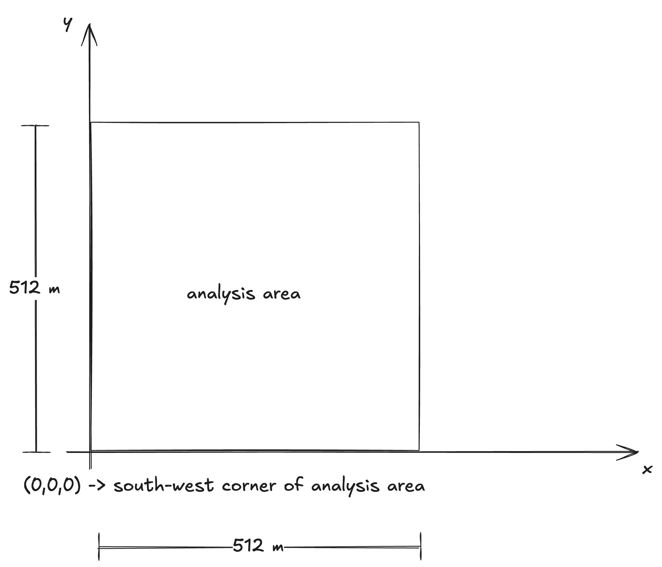
Analysis Area
The analysis area is a 512x512 box that all analyses will be conducted in.
The axis origin (0,0,0) must always be the bottom-left (south-west) corner of the analysis area.
This means that all the mesh coordinates have the south-west corner of the analysis area as reference point.
Mesh Object
All of our simulations run on some sort of geometrical input. We have chosen a universal and open source JSON-like triangular mesh format called dotbim to represent the objects that interact with the infared.city API. Some minor modifications have been done in the in the general structure, which will be explained below.
You can find more information about dotbim meshes here.
The Mesh Object is defined as a JSON object containg the fields coordinates, indices and mesh_id (optional)
- coordinates: A flat list of coordinates for all the vertices of the mesh in the format [X0,Y0,Z0,X1,Y1,Z1, ... Xn,Yn,Zn]
- indices: A flat list of numbers. Each number is the index of a vertex. The indices are used in triplets to form a triangular face. Remember that list are 0-based, meaning that the first element has an index of 0, the second 1 etc.
- mesh_id: an integer >= 0. This field id optional for Infrared.city, as we don't support dotbim elements.
Example: Let's say that we have a mesh that contains a single triangle with the vertices V0 (X0,Y0,Z0), V1 (X1,Y1,Z1), V2 (X2,Y2,Z2). The mesh object in psuedo-code shall look like this:
{
     "coordinates": [
        X0,
        Y0,
        Z0,
        X1,
        Y1,
        Z1,
        X2,
        Y2,
        Z2,
    ],
    "indices": [
        0,
        1,
        2
    ]
}
Example of a pyramid:
{
  "coordinates": [
    0.0,
    0.0,
    0.0,
    10.0,
    0.0,
    0.0,
    10.0,
    10.0,
    0.0,
    0.0,
    10.0,
    0.0,
    5.0,
    5.0,
    4.0
  ],
  "indices": [
    0,
    1,
    2,
    0,
    2,
    3,
    0,
    1,
    4,
    1,
    2,
    4,
    2,
    3,
    4,
    3,
    0,
    4
  ]
}
Geometries Object
The geometries object is a JSON object of the format {"<uuid1>": <MeshObject1>, <uuid2>": <MeshObject2> ... }
The uuid is a unique string of the type uuidv4
The geometries object is the actual object being used do describe the scene geometries. It is present on every request to the run-analysis endpoint. For now Infrared.city makes no differentiation of context and site geometries. All geometries of the scene are included in the geometries object.
Example: Geometry consisting of 2 rectangle meshes:
{
    "226e57e8-3417-4f9d-ad3f-ddc2ce169838":{
        "coordinates":[
            0,
            0,
            0,
            1,
            0,
            0,
            1,
            1,
            0,
            0,
            1,
            0
        ],
        "indices":[
            0,
            2,
            1,
            0,
            3,
            2
        ]
    },
    "6fbf2238-3fba-42a8-b7d0-a7ac1b24a709":{
        "coordinates":[
            5,
            5,
            5,
            6,
            5,
            5,
            6,
            6,
            5,
            5,
            6,
            5
        ],
        "indices":[
            0,
            2,
            1,
            0,
            3,
            2
        ]
    }
}
Best Practices
Here you can find some advice on best practices for Infrared.city, in order to get optimal results.
-
On urban level simulations geometries should be simplified massings. Remove all details and small elements, and reduce the vertex and face count of flat faces to the maximum.
-
Usually meshes with sharp edges and corners duplicate vertices in order to have sepate vertex normals and render the sharp corner. This is only related to mesh rendering, for the analysis purposes of infrared.city we don't need sharp edges, so you can optimise your geometries by "welding" duplicate vertices.
-
Do not add geometries that are fully outside of the analysis area, as they won't be taken into account. Do add geometries that are partially out as normal.
-
The vertex coordinates of the geometry sent should ideally have up to 2 decimal digits. More than that is unnecessary and slows down your analysis.